
Pinouts
GPIO numbers refer to the ESP32-S3 unless labeled C5. The expansion breakout table identifies the processor for every GPIO.
Jump to the base board, expansion breakout connections, or six-C5 expansion add-on. The RF/NFC add-on is in early testing and has no published pin map.
Base Cerberus board
The base board uses an ESP32-S3 N16R2, one onboard ESP32-C5, and 1-bit SDMMC with a 40 MHz maximum clock target.
ST7796 display
| Signal | S3 GPIO | Purpose |
|---|---|---|
| LCD DC | GPIO4 | Command / data selection |
| LCD RESET | GPIO5 | Panel reset |
| LCD BL | GPIO6 | Backlight PWM |
| LCD CS | GPIO16 | SPI2 chip select |
| LCD SCLK | GPIO17 | SPI2 clock |
| LCD MOSI | GPIO18 | Write data to panel |
| LCD MISO | Not used | Display driver is write-only |
Display setup: 320 × 480 portrait, RGB565, SPI2 at 40 MHz. Pixel orientation and inversion belong to the display driver.
GT911 touch and shared I²C
| Signal / device | S3 GPIO / address | Notes |
|---|---|---|
| I²C SDA | GPIO8 | Shared I²C0 data |
| I²C SCL | GPIO9 | Shared I²C0 clock; 400 kHz |
| Touch INT | GPIO7 | Interrupt / initialization signal |
| Touch RESET | Not connected | No dedicated reset GPIO |
| GT911 address | 0x5D |
7-bit I²C address |
| MAX17048 fuel gauge | 0x36 on GPIO8/9 |
Battery voltage and estimated percentage |
| BQ25895 charger | 0x6A on GPIO8/9 |
Shared I²C0: SDA GPIO8, SCL GPIO9; charger control/status |
Register added I²C devices on the existing bus. Check address conflicts and combined pull-up strength.
microSD
| Card signal | S3 GPIO / connection | Notes |
|---|---|---|
| DAT0 | GPIO35 | Single data line |
| CLK | GPIO36 | SDMMC clock; up to 40 MHz |
| CMD | GPIO37 | SDMMC command |
| DAT1 / DAT2 | Board pull-ups | Not used for 1-bit data transfer |
| DAT3 | Board pull-up | Not driven by firmware |
Use 1-bit SDMMC, with SDMMC_FREQ_HIGHSPEED as the 40 MHz maximum configuration. The actual clock is negotiated by the card and firmware. See the SDMMC configuration example.
S3 ↔ onboard C5
| Signal | S3 GPIO | Onboard C5 connection | Direction / mode |
|---|---|---|---|
| SPI CS | GPIO10 | GPIO8 | S3 → C5 |
| SPI MOSI | GPIO11 | GPIO5 | S3 → C5 |
| SPI SCLK | GPIO12 | GPIO4 | S3 → C5 |
| SPI MISO | GPIO13 | GPIO6 | C5 → S3 |
| Runtime READY | GPIO44 | GPIO11 | C5 → S3 |
| Programming UART TX | GPIO43 | GPIO12 / UART RX | S3 → C5; 115200 baud |
| Programming UART RX | GPIO44 | GPIO11 / UART TX | C5 → S3; same wire as READY |
| Reset control | GPIO21 | EN through inverting circuitry | S3 high holds reset; low releases it |
| Boot control | GPIO40 | BOOT through inverting circuitry | S3 high requests download mode at reset |
GPIO44 is driven by the onboard C5. Keep other peripheral outputs off that wire. GPIO43 is the C5 programming TX signal; isolate add-on circuitry using it before C5 flashing.
Native USB and startup
| Signal / restriction | S3 GPIO | Notes |
|---|---|---|
| USB D− | GPIO19 | Native USB |
| USB D+ | GPIO20 | Native USB |
| S3 BOOT | GPIO0 | ROM recovery control |
| Other startup straps | GPIO3, GPIO45, GPIO46 | Preserve required reset states |
| Flash / PSRAM | Module memory connections | Preserve the N16R2 quad-PSRAM configuration |
Expansion breakout connections
Viewing orientation: the labeled face is toward you, with the board's long dimension vertical as shown in the photo. The left labeled row starts higher on the board than the right labeled row.
The breakout exposes 25 GPIO signals: 7 ESP32-C5 and 18 ESP32-S3. Each signal has its own row below, ordered top to bottom on the left side, then the right side. Power and ground contacts are omitted.
View the labeled expansion breakout photo
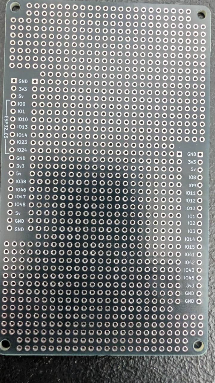
| Processor | GPIO | Printed label | Side |
|---|---|---|---|
| ESP32-C5 | GPIO0 | IO0 | Left |
| ESP32-C5 | GPIO1 | IO1 | Left |
| ESP32-C5 | GPIO10 | IO10 | Left |
| ESP32-C5 | GPIO13 | IO13 | Left |
| ESP32-C5 | GPIO14 | IO14 | Left |
| ESP32-C5 | GPIO23 | IO23 | Left |
| ESP32-C5 | GPIO24 | IO24 | Left |
| ESP32-S3 | GPIO38 | IO38 | Left |
| ESP32-S3 | GPIO46 | IO46 | Left |
| ESP32-S3 | GPIO47 | IO47 | Left |
| ESP32-S3 | GPIO48 | IO48 | Left |
| ESP32-S3 | GPIO8 | IO8 | Right |
| ESP32-S3 | GPIO9 | IO9 | Right |
| ESP32-S3 | GPIO11 | IO11 | Right |
| ESP32-S3 | GPIO12 | IO12 | Right |
| ESP32-S3 | GPIO13 | IO13 | Right |
| ESP32-S3 | GPIO1 | IO1 | Right |
| ESP32-S3 | GPIO2 | IO2 | Right |
| ESP32-S3 | GPIO3 | IO3 | Right |
| ESP32-S3 | GPIO14 | IO14 | Right |
| ESP32-S3 | GPIO15 | IO15 | Right |
| ESP32-S3 | GPIO41 | IO41 | Right |
| ESP32-S3 | GPIO42 | IO42 | Right |
| ESP32-S3 | GPIO43 | IO43 | Right |
| ESP32-S3 | GPIO45 | IO45 | Right |
The ESP32-C5 bracket covers the seven upper-left GPIOs. All remaining GPIOs are ESP32-S3 connections. A GPIO number on the C5 is a separate signal from the same number on the S3.
The S3 SPI and I²C contacts share their base-board buses. Preserve the bus settings and startup-strapping requirements described above.
Download the expansion breakout CSV · Open the full-size photo
Six-C5 expansion add-on — in testing
Optional expansion add-on · In testing. This board adds six WROOM C5 radios to the base board's onboard C5. Matching add-on firmware is required.
S3 bus and radio selects
| Signal | S3 GPIO | Notes |
|---|---|---|
| Shared MOSI | GPIO11 | S3 → all C5 radios |
| Shared SCLK | GPIO12 | S3 → all C5 radios |
| Shared MISO | GPIO13 | Selected C5 → S3 |
| R0 onboard C5 CS | GPIO10 | Base-board radio |
| R1 add-on C5 CS | GPIO14 | Expansion radio 1 |
| R2 add-on C5 CS | GPIO15 | Expansion radio 2 |
| R3 add-on C5 CS | GPIO41 | Expansion radio 3 |
| R4 add-on C5 CS | GPIO42 | Expansion radio 4 |
| R5 add-on C5 CS | GPIO45 | Expansion radio 5 |
| R6 add-on C5 CS | GPIO48 | Expansion radio 6 |
WROOM C5 module side
| Signal | Expansion C5 GPIO | S3 connection |
|---|---|---|
| MOSI input | GPIO10 | S3 GPIO11 |
| SCLK | GPIO8 | S3 GPIO12 |
| MISO output | GPIO9 | S3 GPIO13 |
| CS | GPIO23 | Assigned S3 radio-select slot above |
Each expansion C5 uses the c5-expansion-wroom image; its radio identity follows the S3 chip-select slot. The memory baseline is 4 MB flash / no PSRAM. Programming checks have passed on six modules; assembled multi-radio operation remains in testing.
Download the six-C5 expansion pinout CSV.
Developer files
The expansion breakout table lists GPIO signals as viewed from the labeled face. Connector part number, pitch, and current ratings are not specified here.
Download the base-board pin header. The expansion add-ons page has testing status, bus integration notes, and the expansion KiCad file area.
Base-board source: Cerberus pin definitions. The six-C5 expansion mapping above remains in testing.